Sunday, February 15, 2015

Micro Servo Motor - calibrating position angles

I want to use a rather typical micro servo motor to move the eyes of my rover to "look" side to side and determine if there is an object present. I received the 3D prints this week for the servo mounting and the ultrasonic distance sensor so it's time to make sure my micro servo control works as planned. I'm going to use a Arduino Micro and some simple code with a basic bread board to bring the servo to life and tweak the positioning.
Parts Needed: 
1 Breadboard
1 Arduino Micro (or other Arduino board) ($24.95)
3 wires (female to female)
1 Micro Servo Motor  ($12.99)
1 USB to Micro USB cable ($9.99)  you might already have one from your smart phone


There are only three wires to connect so the hook up is easy... 
Here is the pin mapping:

Micro Pin    Servo Connection
Grd         --> Brown Wire
5V          --> Red Wire
 9            --> Yellow Wire

Insert the Arduino Micro into the breadboard and connect the ground, 5 volt and pin 9 to the servo motor as shown above. 

Upload the code to and and tweak the servo position values until they match your setup.. Get the code here.. MicroServoCalibration Code


Sunday, January 4, 2015

SainSmart Mega 2560 R3 4WD Mobile Car Robot Kit Build


Assembled Rover
I got a SainSmart Mobile Car Robot Kit for Christmas so I thought I'd share the build experience. The kit costs about $95 and it doesn't come with any instructions. However, thanks to some other makers out there, I found some helpful instructions posted on Instructables and also a useful post about it on Thingiverse.

There were a few problems with this kit. I wouldn't recommend getting this kit unless you have some experience. Some of the screw holes in the metal frame don't line up very well, but that was pretty minor. The biggest problems are that it doesn't come with enough wire and several of the parts in the kit were bad. In my kit, the Mega 2560 wouldn't accept code uploads and the reset button on it didn't work at all. Also, the battery pack had a short so when I hooked it up it started smoking.

Fortunately, I was able to use an Arduino Mega, some 9 volt battery connectors, and extra wire I already had. Hopefully SainSmart will send me a functional Mega to replace the non-working board in my kit. There is also nothing to mount the distance sensor and no hook up wires for it, so you'll have to get creative if you want to use it.

Parts List from the Kit: 

4 wheels
4 motors
2 rounded metal plates fro the front and back
2 side plates
2 flat plates for the top and bottom of the case
A bunch of screws
2 wires (1 red, 1 black)
1 4-wire female to female connection harness
1 battery pack
1 toggle switch
1 re-charge connector
1 USB cable
1 SainSmart MEGA 2560 R3
1 SainSmart Sensor Sheild V5
1 SainSmart L298N Dual H Bridge DC motor driver
1 HC-SR04 Distance Sensor


Other Items you'll need: 

2 9 volt batteries
2 9 volt battery connectors
extra wire
solder and a soldering iron
electrical tape
wire strippers
A volt meter

Build it ..

STEP 1: Hook up the Toggle Switch and connect the battery leads to the L298N Motor Driver

  1. Place the toggle switch in one of the holes on the top plate and use the washer and nut (only one fits) to secure it in place. 
  2. Secure the L298N Motor Driver to the bottom plate using the screws provided. (The wholes in the plate should line up pretty will with the mounting wholes on the board.)
  3. Connect the battery connectors together in series by soldering the ends of the black lead on one connector to the red lead on the second connector. Use electrical tape to cover the connection.
  4. Connect/solder the remaining red lead on the first battery connector to the center lead on the toggle switch.
  5. Connect the remaining black lead on the other battery connector to the screw connector on the Motor Driver labeled Gnd (The ground pin). 
  6. Cut a 4 inch piece of the red wire that came in the kit and strip away the sheath on the end to expose the wire on the cut side. Connect one side of this wire to one of the side leads on the toggle switch. Connect the other end to the to the screw connector labeled Vcc on the Motor Driver board. 
  7. Test the toggle switch connections and make sure it works.
    With the switch in the off position, connect the batteries. Then flip the switch to the on position. If your connections are good, the red led on the Motor Driver board should light up. if it doesn't, check the connections and try again. 
  8. Turn the switch off and disconnect the batteries. 


STEP 2: Connect the Motors to the Motor Driver


  1. Cut 2 4 inch wires from the red wire, and 2 4 inch wires from the black wire. 
  2. Cut 2 6 inch wires from the red wire and 2 6 inch wires from the black wire. 
  3. Strip the ends of each of the wires. 
  4. Solder the 4 inch black wire to one of the leads on the first motor, and the 4 inch red wire to the other lead on the first motor. 
  5. Solder the the 6 inch wires (one red and one black) to the second motor for the same side as shown in the picture. Caution: Take care to make sure that the wire colors match the orientation in the picture so that the wheels will both spin in the same direction. 
  6. Secure The motors to the side plate and secure the side plate to the bottom plate using the screws provided. 
  7. Connect the red leads for the two motors to one of the screw connection ports on the Motor Driver board labeled out. 
  8. Connect the black leads for the two motors to the other out port on the same side of the Motor Driver board. 

Repeat this process for the remaining two motors on the other side.


STEP 3: Connect the remaining wires to the Motor Driver board


  1. Cut and strip two wires (black and red preferred) to be used as ground and voltage supply wires for the Arduino. These wires will need to be about 6-7 inches long. 
  2. Connect the black wire to the ground on the Motor Driver board using the screw connector. 
  3. Connect the red wire to the 5V screw connector on the Motor Driver board.
  4. Using the 4 wire harness, connect the wires to the INT pins on the Motor Driver board as follows:
    INT1 -> Red 
    Switch and INT pin Connections
    INT2 -> Brown
    INT3 -> Black
    INT4 -> White


  1. Re-connect the batteries, but leave the switch off for now. 
  2. Fish the power, ground and 4 wire harness wires through the top plate from the bottom side.
  3. Place the top plate on top of the two sides where it will eventually be screwed on.

STEP 4: Program the Mega Using the Arduino IDE

The great thing about the Motor Driver board, is that for on and off control of the motor, you don't need any external libraries, just set the pins HIGH and LOW to control the direction of the motors. 

Copy the following code upload it to the Mega board using the Arduino IDE. 

//declaring the pins for the IN pins on the L298N
const int rightForwardPin = 4;
const int rightBackwardPin = 2;
const int leftBackwardPin = 7;
const int leftForwardPin = 5;

int runTime = 1000;

void setup() {
  //Stating that the pins are OUTPUT
  pinMode(rightForwardPin, OUTPUT);
  pinMode(rightBackwardPin, OUTPUT);
  pinMode(leftForwardPin, OUTPUT);
  pinMode(leftBackwardPin, OUTPUT);
}

//Looping to test the wheels of the car
void loop() {
  forward();
  stopCar();
  backward();
  stopCar();
  left();
  stopCar();
  right();
  stopCar();
}

//Setting the wheels to go forward by setting the forward pins to HIGH
void forward(){
  digitalWrite(rightForwardPin, HIGH);
  digitalWrite(rightBackwardPin, LOW);
  digitalWrite(leftForwardPin, HIGH);
  digitalWrite(leftBackwardPin, LOW);
  delay(runTime);
}

//Setting the wheels to go backward by setting the backward pins to HIGH
void backward(){
  digitalWrite(rightForwardPin, LOW);
  digitalWrite(rightBackwardPin, HIGH);
  digitalWrite(leftForwardPin, LOW);
  digitalWrite(leftBackwardPin, HIGH);
  delay(runTime);
}

//Setting the wheels to go right by setting the rightBackwardPin and leftForwardPin to HIGH
void right(){
  digitalWrite(rightForwardPin, LOW);
  digitalWrite(rightBackwardPin, HIGH);
  digitalWrite(leftForwardPin, HIGH);
  digitalWrite(leftBackwardPin, LOW);
  delay(runTime);
}

//Setting the wheels to go left by setting the rightForwardPin and leftBackwardPin to HIGH
void left(){
  digitalWrite(rightForwardPin, HIGH);
  digitalWrite(rightBackwardPin, LOW);
  digitalWrite(leftForwardPin, LOW);
  digitalWrite(leftBackwardPin, HIGH);
  delay(runTime);
}

//Setting the wheels to go stop by setting all the pins to LOW
void stopCar(){
  digitalWrite(rightForwardPin, LOW);
  digitalWrite(rightBackwardPin, LOW);
  digitalWrite(leftForwardPin, LOW);
  digitalWrite(leftBackwardPin, LOW);
  delay(1000);
}

STEP 5: Connect the Sensor Shield and Mega to the Circuit 

  1. Place the sensor shield on the Mega making sure the connection pins are placed in the correct slots. 
  2. Connect the 5V power line to the Vcc screw connection terminal on the Sensor Shield. 
  3. Connect the Ground line to the GND ground screw connection terminal on the Sensor Shield. 
  4. Connect the 4 wire harness to the following pins on the Sensor Shield:
    Red - > pin 7
    Brown -> pin 5
    Black -> pin 4
    White -> pin 2
Sensor Shield Connections

STEP 6: Test It 

Now with all the connections made, it's time to see if works.
  1. Secure the top plate and secure the Mega board to the top plate (using the small screws). 
  2. Turn the switch to the ON position. 
  3. The motors should start to turn soon after it is turned on.
  4. The green LED on the Mega board should come on and a red LED may be lite or flashing on the Sensor Shield, indicating that is has power. If there is no power,  try pushing the button on the Motor Driver board to turn on the external power.
  5. Verify the direction that the motors are turning in. Both motors on any given side should always turn in the same direction. 

If everything is working, Attach the wheels and finish securing the front and back metal plates. 


Saturday, September 13, 2014

Building a Color Sensor using the Adafruit TCS34725 and an ATMega32A Microprocressor

This project uses the Adafruit TCS34725 RGB Color Sensor and an ATMega32A microprocessor to collect and display color data in a WPF application.

The TCS34725 RGB color sensor is a neat little sensor. The sensor itself uses a photo-diode array with red, green and blue filters to measure color temperatures in Kelvin. The Adafruit library takes care of communications with the sensor, and converts the color temperatures to familiar RGB values. The Adafruit breakout for the sensor also includes a white led to illuminate objects so you can use the sensor for reflected light from colored objects when the light is on, or turn the light off and use the sensor to detect the color of light emitted from an external source (such as an RGB led). I use a push button to make it easy to toggle the led on or off.


Parts List


ATMega32A-PU   ($3.15)
USB to TTL Serial cable ($9.95)
TCS34725 RGB Color Sensor ($7.95)
A tactile switch button ($2.50 for 10 pack)
A 10k Resistor ($0.25)
Perma-Proto half-sized breadboard PCB ($4.50) (optional)

Estimated Cost ~$26

Additional Hardware Tools Need


An ISP Programmer or an Arduino Board to use as an ISP Programmer
A breadboard and some wires
A soldering iron (optional)
A 10pF capacitor if using the Arduino as an ISP Programmer

Downloads

Arduino IDE 
Visual Studio Express 2010 (with C#)
ATMega32 board and pin files
Adafruit_TCS34725 library
Color Sensor sketch for ATMega32
Color Sensor WPF Application


Step 1: Environment Setup


  1. Download the Arduino IDE and install it (if you don't have it already)
  2. Install the boards and pins files for the ATMega32 to the Arduino IDE
  • Download the ATMega32 board and pin files
  • Create a folder named mega32 in the directory:
           C:\Program Files (x86)\Arduino\hardware\arduino\variants
  • Copy the arduino_pins.h file to the folder you created:
           C:\Program Files (x86)\Arduino\hardware\arduino\variants\mega32
  • Copy the text from the boards.txt file and past it into the boards.txt located at:
           C:\Program Files (x86)\Arduino\hardware\arduino\boards.txt
  • Open the Arduino IDE. You should now see the ATMega32 boards under the
    Tools -> Board  menu.  Select ATMega32 - 1mhz

Step 2: Program the ATMega32 with the color sensor sketch


If using an arduino as an ISP:


  • Upload the ArduinoISP sketch from  File->Examples -> ArduinoISP in the Arduino IDE.
  • Set up the circuit for to use the Arduino as an ISP programmer by making the following connections:

Arduino Mega/ Uno Pins to ATMEGA32A Pins
MISO pin 50/ pin 12->pin 7 MISO
MOSI pin 51/ pin 11->pin 6 MOSI
CLK pin 52/ pin 13->pin 8 SCK
SS pin 53/ pin 10->pin 9 RESET
5V->pin 10 VCC
GND->pin 11 GND
RESET to Capacitor to->GND

  • Under Tools->Programmer select the "Arduino as ISP" option.
If you are using another flash programmer, select the appropriate option for your device.

Next, upload the Color Sensor stetch to the ATMega32:
  1. Download and Install the Adafruit_TCS34725 library to your Arduino IDE.
  2. Download the Color Sensor Sketch and open it in the Arduino IDE. 
  3. Select "ATMega32 - 1mhz" as your board under Tools -> Board. 
  4. Make sure the Serial Port is selected under the Tools menu.
  5. Press Ctrl + Shift + U to upload the code using a programmer. 

If everything worked you should see the message "avrdude done. Thank you.".


Step 3: Setup the Color Sensor Circuit


Now that the ATMega32 is programmed for the Color Sensor, lets set up the circuit and test it out. The diagram below shows the circuit connects for the sensor. The power is supplied by the USB to TTL cable through the USB port. The circuit connections needed are shown in the diagram below.
Color Sensor Circuit Connections

Step 4: Test the Circuit with the Color Sensor WPF application


Download the Color Sensor WPF Application.
Open the solution file in Visual Studio 2010 Express and compile it. Here is the link to download and install Visual Studio Express 2010 (with C#) if you do not have it.
Plug in the USB to TTL Serial cable to your computer.
The led light on the color sensor will come on at this time. If your circuit is correct, you should be able to turn it off by pressing the button.
Windows should automatically recognize the serial connection and assign it to a COM port. You can see which COM port it is on either by looking in  the Device Manager under Ports (COM and LPT) or in the Arduino IDE the COM port will show up as a selection under Tools->Serial Port.

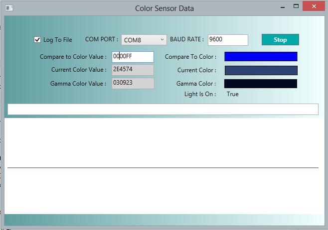
If everything worked so far, it's time to run the Color Sensor application. You can run the application in debug mode by pressing F5 in Visual Studio if you still have the solution open.  It should look something like picture below:

ColorSensor-WPF application running in Debug Mode

Select the correct COM port for your USB to Serial TTL cable and press the Start button to begin receiving color data from the color sensor.
After you press the Start button, you will see the Current Color and Gamma Color change based on the colors detected by the sensor!

Step 5; Experiment with the the Color Sensor using different colored objects


If you want to see the color of an object that does not emit light such as a notebook then press the button on the sensor a few times until the led light ON.
With the light on, try holding different colored objects up to the sensor so that the led light is reflected back onto the adjacent sensor array.
Notice the color show in Current Color compared to the actual object color? The color sensor is better at detecting some colors than others..

It is pretty good at detecting that a color is blue.. Here is the result when I held a blue Nivea lotion bottle directly up to the sensor. I set the Compare to Color Value to pure blue for an reference color. The Gamma Color Value doesn't seem to be closer for these purposes. It seems much darker.

The Current Color is the color detected when a blue object was held up to the sensor.

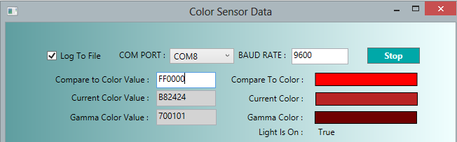
Now I'd like to try a few other object colors. here is the screen shot from the output from a red ball.
The Current Color is from a Red Ball held up to the Sensor.
Red and Blue are not perfect, but they are at least in the right range, lets try green.Green is not too bad but not perfect either. 


So what about mixed colors like yellow?  Here is what it looks like when I hold a yellow object next to the sensor:

The yellow object appears more olive green than yellow. It seems to detect more green from the yellow, but not enough red to show the yellow. Hopefully I can find a way to adjust the colors so they are closer to those of the actual object. The gamma corrected color doesn't seem like it's going to help here either, it still appears too dark.


Other References


The AMS Light Sensors product Website - Look under Technical Documentation. There are several documents that explain the science in measuring and converting color temperature to RGB values. If you dig into the Adafruit library, you will see the formula's there come from this documentation.

TCS34725 color sensor data sheet
TAOS Inc (now AMS)


Sunday, August 24, 2014

Setting up the Toolchain for Atmel AVR programming in Windows

The basic setup for an open source toolchain will get you pretty far in programming Atmel AVR's that are supported by avr-gcc. If you want to program these AVR's directly using standard c code, you'll need a toolchain, plus some hardware.  Here are my notes for setting this up on a Windows 8 machine.

Hardware Needed:

  1. ATMega32A - PU (the PU package is breadboard friendly)
  2. An ISP / USB Flash Programmer -
    This is a USB device that allows you to send compiled hex files down from your computer to the chip. The device uses the SPI interface and  reset on the chip to load code onto the chip. I've been using my Arduino Mega for this.
  3. Some basic hardware: A Breadboard, an LED, and some wires for testing.

Software Needed:

  1. Notepad++  (You could also use Programmers Notepad that is included with the WinAVR suite or another IDE to edit and write your code).
  2. WinAVR - This is an open source suite of compiler tools that includes the compiler and AVRDUDE uploader software in one great package
    •  avr-gcc - this a compiler you can use to compile c  and c++ code and turn it into a hex file that can be run on an ATmel AVR 
    • AVRDUDE - This is the software tool that understands how to make your flash programmer upload your hex compiled code to your AVR chip.
  3. make file - these are text files that allow you to run all the tools in one easy step from from compiling your c code with avr-gcc to uploading it with AVRDUDE
  4. Code to upload and test with.


Step 1: Install WinAVR

  1. Download WinAVR and install it on your computer.
    You can download WinAVR from sourceforge by clicking here.
  2. Download Notepad++ and install it on your computer (or use another editor).
    You can download Notepad++ here


Step 2:  The Makefile

A make file is sort of like a script (or batch file) that can help you compile your code and then do other stuff too. In this case, it's going to compile your code and if your circuit connections are good, it's going to upload your code to the AVR chip! Sweet right!?! The easiest way to get started with make files is to start with one that already does most of what you want it and customize it for your needs.
Click here to download a Makefile and blink.c code to test with.

The make file contains only a few items that need to be changed. These are items specific to the type of programmer being used, the target avr chip, and the source code being compiled and uploaded.

Target AVR Flags:

MCU = atmega32    
F_CPU = 1000000
BAUD = 9600

MCU :   This tells avr-gcc what target to compile the code for.  In this case the target is an atmega32. To find out what other targets are supported just go to the command prompt and type:
  avr-gcc --target-help
F_CPU :   This tells avr-gcc the clock frequency in Hertz for the target AVR. This needs to be correct for anything timing related to work properly. Note: this does not set the clock frequency! It just tells avr-gcc what the frequency is. The specifics of the clock operations can be found by searching for "System Clock and Clock Options" in the ATMega32 Datasheet. It may be a bit daunting, but basically it tells you that the default clock source is set to 1 MHz.
BAUD : This is the baud rate used for serial communications between the avr and your computer. This just tells the avr what speed you want to talk at. The avr may support higher baud rates that are documented in the datasheet. 9600 is a safe default.

Source Code specifiers:

MAIN = blink.c
LOCAL_SOURCE = blink.h
EXTRA_SOURCE_DIR = ..\..\lib
EXTRA_SOURCE_FILES = myotherfile.c

MAIN:  The source file that contains your main function.
LOCAL_SOURCE:               Additional code files in the same directory as your main file.
EXTRA_SOURCE_DIR :      Specify another directory to look for source files.
EXTRA_SOURCE_FILES:   Specify additional source files to include.

Every Make file usually has some way of specifying these, although it often has different variables than the ones above. Check out the one make file template included with WinAVR to see one that is very different.

 Programmer Flags:

PROGRAMMER_TYPE = avrisp
PROGRAMMER_ARGS = -v -v -cstk500v1 -P\\.\COM4 -b19200

PROGRAMMER_TYPE :    This is the name that tells avrdude what programmer you are using. To find out what programmer options are supported in avrdude go to the command prompt and type:
avrdude -c ?
PROGRAMMER_ARGS :   These are all the other arguments that will be passed to avrdude. Depending on the type of programmer you use. To use the arduino as an ISP, I need to specify that the Arduino is on COM4, and that the ISP programmer code uses a baud rate of 19200. Also stk500v1 tells it to use the Atmel STK 500 version 1 and -v -v tells it to give verbose output.

STEP 3: Circuit Setup - Arduino as an ISP programmer

The circuit setup is the same as it was to program the ATTIN84A except that the pins are different on the ATMega32A.

Arduino Mega/ Uno Pins to ATMEGA32A Pins
MISO pin 50/ pin 12->pin 7 MISO
MOSI pin 51/ pin 11->pin 6 MOSI
CLK pin 52/ pin 13->pin 8 SCK
SS pin 53/ pin 10->pin 9 RESET
5V->pin 10 VCC
GND->pin 11 GND
RESET to Capacitor to->GND


STEP 4:  Program the Arduino as an ISP programmer

To turn the Arduino Mega into an AVR ISP you need to upload the  ArduinoISP sketch to your Arduino board.
  1. Using the USB cable, connect your Arduino Mega 2560 or Arduino Uno to your computer.
  2. Open the the Arduino IDE. 
  3. Under Tools -> Boards select the "Arduino Mega 2560" (or select "Arduino Uno" if you are using that instead) as the board.
  4. Under Tools -> Programmer select "AVR ISP"
  5. Select File -> Examples -> ArduinoISP to open the Arduino ISP sketch. 
  6. Compile the sketch and upload it to your Arduino Board. 
   Your Arduino is now ready to use as an in system programmer!

STEP 5: Run the Makefile 

Now we are ready to test it out. 
  1. Make sure the COM port in the make file  PROGRAMMER_ARGS matches the one the Arduino is connected to. (It is currently set to COM4 in the make file).
  2. Once the COM port is correct, go to the command line in the directory where the Makefile and blink.c are extracted.  On the command line type:
    make flash
   If it works you should see a lot of output with no errors. At the end it should say:
   avrdude done.  Thank you.
 
If you get an error, check your circuit and make sure the connections are correct. Also verify the COM port is correct,  and verify the baud rate matches the ArduinoISP sketch.

STEP 6: Test the blink code on the ATMega32 with an LED

If everything else worked above, connect an LED from Pin 1 (PB0) to ground.  And it blinks!


Saturday, August 23, 2014

Bit Twiddling Reference for AVR programmers

If you do any AVR programming in c or c++, you'll very likely need these operations. As often as I've seen them, I still sometimes need to look these up if I haven't used them in a while. So here they are...

Assume that the variable myByte is a 8 bit variable defined as the following in c code:
                                                                  byte myByte = 0x00;

The above line of code sets all 8 bits (0-7) to 0, turning them all OFF using the hex notation.

Set bit  i (ON/1):                          myByte |= (1 << );

Clear bit  (OFF/0):                    myByte &= ~(1 << );

Toggle bit                                myByte ^= (1 << );


Saturday, July 26, 2014

Use an Arduino Mega 2560 to program an ATTINY84A

This is a hello world AVR programming project. A simple way to get started programming an inexpensive AVR chip for anyone who has an Arduino board. I am going to use an Arduino Mega 2560 as an ISP AVR programmer but you can also do this with an Arduino UNO or any board with a SPI interface if you know how. 

If you have been working with some developer boards like the Arduino UNO or the Arduino Mega 2560, and you are comfortable soldering your own projects, then you might have realized that the chips alone usually cost from $1-$3 and take up a lot less space than the breakout boards do.  The good news is, you can easily get started programming these chips using the developer board that you have on hand! 


For this example, I am going to use my Arduino Mega 2560 as an ISP AVR programmer to program an  ATTINY84A-PU chip to do a simple LED blink. There are other ways to program this chip, but if you happen to already have an Arduino board on hand and don't want to spend the extra money to buy a programmer, this is a quick and easy way to get started.  


Parts List: 

  1. 10mm Ultra-High Brightness Blue LED - any LED will work
  2. An Arduino Mega 2560  or UNO 
  3. A 10uF capacitor
  4. An ATTINY84A-PU  ($1.41)
  5. Small Breadboard
  6. Connection Wires

The first thing you need to do is be able to program your chip using the Arduino Mega. To do that with the Arduino IDE you will need to install the Tiny bootloader and supporting libraries into the Arduino IDE. Then you will need to set up the circuit for the programmer, upload a blink sketch to the chip, and finally, setup the chip circuit to work with the blink circuit.

Using the Arduino Mega as an AVR programmer


Step 1: Prepare the Arduino IDE environment to program the ATTINY84A 

You need to be able to compile code into a hex file to load onto the ATTINY84A and upload that code from the Arduino IDE but the functionality to do that requires some additional software components that are not included by default.


  1. Click here to download the "Tiny" archive 
  2. Create a new directory named tiny under your ..\Arduino\hardware directory.
    For newer versions of the Arduino IDE, this may be located in:
         "C:\Program Files (x86)\Arduino\hardware"
  3. Copy and paste the contents of the tiny/avr directory of the archive to the ..\Arduino\hardware\tiny directory you created.
  4. In the  ..\Arduino\hardware\tiny directory, rename the Prospective Boards.txt file to boards.txt
  5. Open the Arduino IDE. You should see the ATTINY84 under the Tools->Boards menu.


Step 2: Program the Arduino Mega 2560 to be an AVR ISP

To turn the Arduino Mega into an AVR ISP you need to upload the  ArduinoISP sketch to your Arduino board.
  1. Using the USB cable, connect your Arduino Mega 2560 or Arduino Uno to your computer.
  2. Open the the Arduino IDE. 
  3. Under Tools -> Boards select the "Arduino Mega 2560" (or select "Arduino Uno" if you are using that instead) as the board.
  4. Under Tools -> Programmer select "AVR ISP"
  5. Select File -> Examples -> ArduinoISP to open the Arduino ISP sketch. 
  6. Compile the sketch and upload it to your Arduino Board. 
   Your Arduino is now ready to use as an in system programmer!


 Step 3: Hardware Setup to use the Arduino ISP (for the ATtiny84)


Next we need to make the connections between the Arduino Mega (or Uno) and your ATTINY84A chip.
The Arduino Mega has a hardware SPI interface on pins 50 - 53 that can be used to program other chips like the ATTINY84A as shown in the picture below. (If you are using the Uno, pins 50, 51, 52, and 53 on the Mega should be mapped to pins 12, 11, 13, and 10 on the Uno). 

Arduino Mega 2560 Hardware SPI Pins
(note: we also use pin 53 - the SS pin to reset to ATtiny84)

We need to connect the SPI pins from our Arduino to the SPI pins on the ATTINY84A. I am using the ATTINY84A-PU because the PU extension chips are breadboard friendly. The pins needed for this on the ATTINY84A are shown below.

ATTINY84A SPI / ISP Pins
(note: the RESET Pin 4 will also be needed)


Curcuit setup for the ISP AVR programmer


Unplug the Arduino Board and make the following connections:

Arduino Mega/ Uno Pins to  ATTINY84A Pins
MISO pin 50/ pin 12 ->pin 8
MOSI pin 51/ pin 11 ->pin 7
CLK pin 52/ pin 13 ->pin 9
SS pin 53/ pin 10 ->pin 4
5V ->pin 1 VCC
GND ->pin 14 GND
RESET to Capacitor to ->GND


Step 4: Use the AruinoAVR ISP to program the ATTINY84A


  1. Plug in the USB connection for Arduino board to your computer.
  2. Open the Arduino IDE.
  3. Open the Arduino Blink sketch by selecting
              File -> Examples -> Basics -> Blink.
  4. Change the led pin in the blink sketch by changing
                       "int led = 13;" to "int led = 1;"
  5. Select the ATtiny84 @ 8 MHz Internal Oscillator by selecting
              Tools -> Boards ->  ATtiny84 @ 8 MHz Internal Oscillator

    (Caution: Do not select the External oscillator unless you have added an external oscillator; this can cause issues if selected by mistake).
  6. Choose the Arduino as an ISP programmer by selecting
               Tools-> Programmer-> "Arduino as ISP"
  7. Upload the sketch to the chip by selecting
               File-> "Upload Using Programmer" or pressing Ctrl +Shift + U.

Step 5: ATTINY84A-PU LED Blink Hardware Setup

This is the easiest part.. connect the LED o Pin 3 of the ATtiny84, connect the power and ground pins and you will see the LED blink on and off slowly.

Make the connections:

   ATtiny84 Vcc Pin 1     -> 3.5V to 5V source voltage
   ATtiny84 GND Pin 14 -> Ground
   ATtiny84 Pin 3 /PB1     -> LED +
                            LED-  -> Ground


I used a Lipo battery I had to power it but you could also power it from the Arduino 5V, or another power source you might have.


Here is another useful link with more details for doing this with the UNO.
Using the Arduino Uno to program ATTINY84-20PU

Sunday, June 29, 2014

LPD8806 RGB Light Strips - Using an Arduino Mega to count the pixels

The goal of this project is to count the number of LED pixels on a  LPD8806 light strip using SPI MISO and the DO (Data Out) pin at the end of the strip. I used the hardware SPI pins on the Arduino Mega 2560 because it is faster and more reliable than a bit banged software SPI. The code will send data to the light strip increasing the number of pixels on the strip each time until it reaches a maximum number of pixels specified in the code, or until data is found in the Arduino's SPI MISO buffer.  I used 100 as the maximum but this could be changed to any number.

This technique can be used to connect a strip of any length and dynamically determine the number of LED pixels on the strip at start up. This allows for trading out light strips of different lengths without changing the code, as long as the maximum number of LED pixels set in the code is greater than the number of the longest light strip that might be used.

The disadvantage of this technique is that you need a physical connection to the end of the light strip. It would be really cool if they added a 5th connection to the strip that was pass through. Then the DO at the end of the strip could be connected to the pass through line and all the connections here could be at the beginning of the strip.

Click Here to get the Code

LPD8806 RGB Light Strips and SPI 

The LDP8806 light strips are used as a slave device on a SPI bus to transfer data to each pixel in the strip.The hardware SPI (Serial Peripheral Interface) available on the Arduino Mega 2560 is on Pins 50, 51, and 52. The Arduino is the master device, and the light strip is the slave device.

As shown in the image below, pin 52 is the CLK (Clock), pin 51 is the MOSI (Master Out Slave In), and pin 50 is the MISO (Master In Slave Out). The MOSI and CLK pins are used to send data to the light strip. The MISO pin will be used to receive data from the light strip.

Arduino Mega 2560 Hardware SPI Pins

The light strip has 4 connections at the beginning of the strip labeled GND, DI, CI, and +5V and 4 connections at the end of the strip labeled GND, DO, CO and +5V. The connections at the beginning of the strip are used to send data to the light strip and power the light strip. The DO pin at the end of the strip is used to receive data back from the strip.


LPD8806 RGB Light Strip Pins
Light Strip Data
At the beginning of the light strip, the DI and CI pins are the Data In and Clock In pins. The DI pin is connected to the Arduino MOSI (pin 51) and the CI pin is connected to the Arduino CLK (pin 52).
The DO pin at the end of the strip is connected to the MISO (pin 50) on the Arduino. If this pin is not connected, you will never receive data back from the strip!

Powering the Light Strips
The light strip requires an external 5 volt power supply. The Arduino cannot supply enough power to run these strips.


Step 1: Making the Hardware Connections

Parts Needed:


  1. Arduino Mega 2560 ($16)
  2. LPD8806 RGB LED Light Strip ($30)
  3. Power Supply to supply 5 Volts to light strip - I used an old PC power supply but this one will also work, Power Supply + 5 volts ($8) 
  4. You may also need connectors to connect the power supply to your bread board depending on your setup
  5. A bread board 
  6. Some connection wires
  7. A Soldering Iron  (to make connections to the light strip)
  8. A voltage meter to measure supply voltages and ensure they are at or around 5 volts. 


Here is the diagram of the circuit I used: 
Circuit Diagram: LPD8806 RGB LED Light Strip and Arduino Mega

Connections:

Connections at the START side of the Light Strip
  1. Identify the START side of the light strip, this is the side with the labels DI, and CI on the two center connection pads. Connect the GND on START side of the light strip to the power source GND on the bread board. 
  2. Connect the +5V pad on the START side of light strip to the power source +5V on the bread board.
  3. Connect the DI pad on the START side of the light strip to the Arduino Mega's MOSI (pin 51). 
  4. Connect the CI pad on the START side of the light strip to the Arduino Mega's CLK (pin 52). 

Connections at the END side of the Light Strip
  1. Connect the DO pad on the END side of the light strip to the Arduino Mega's MISO (pin 50).
  2. Optionally, you can also connect the GND and +5V on the END side of the light strip to the power source GND and +5V.

Additional Arduino Connections
  1. Connect the Arduino Mega GND pin to the GND from the power source. 
  2. Plug in the USB connection from the Arduino to your Computer.
Make sure the power to your power source is turned on. 

Step 2: Loading and Running the code

  1. Click here to download the sketch for the Arduino
  2. Open the Sketch in the Arduino IDE. 
  3. Select the Arduino Mega 2560 under Tools->Boards in the Arduino IDE
  4. Make sure the Port for the Arduino is selected under Serial Ports
  5. Change  the maxLEDs value in the code to your preferred maximum. This should be a number larger than the largest number of LED pixels any of your LED strips might have.
  6. Compile and Upload the sketch. The code will start running immediately and the LED's on the light strip should turn blue one by one. 
  7. Open the the Serial Monitor from the Arduino IDE to see the output from the code. If everything is wired correctly, you should see the following line at the end of the output with the correct number of pixels for your light strip:
             "Found 64 LED pixels in the strip.
  8. If the MISO/DO connection is not connected, then the following line will be seen at the end of the output:
    "No Data received after testing the maximum number of LEDs 100 Is the DO on the light strip connected to the MISO pin?"


Sunday, May 18, 2014

Teensy 3.1 Accelerometer - Control a Game Object in Unity

Getting the accelerometer data from the Teensy is nice, but the WPF application with some lines on the screen was sort of boring. I wanted to do something more fun with the Teensy 3.1 Accelerometer - use it as a game controller!  So this project is all about using the Teensy 3.1 Accelerometer to control an airplane on the screen using the Unity game development suite.


Hardware Setup

  1. Follow the instructions to build the Teensy 3.1 Accelerometer. This will be used as the game controller through a  USB serial connection.
  2. Note: the Unity game expects the Accelerometer's x, y, and z axis' to be oriented with the Y-axis arrow pointing to the right of the user and the X-axis arrow pointing toward the user when the circuit is in use. 


Software Setup

  1. Download and install the Unity game development suite. (this takes a while, it's a big download)

Now lets take a get the Unity project working.

Step 1 - Download the Unity Plane Game project.

  1. Download the UnityPlaneGame.zip file and extract it to a UnityPlaneGame directory. 
  2. Create an Assets directory under the UnityPlaneGame directory that was just created on your local drive.
  3. Download everything in the UnityPlaneGame/Assets directory of the repository and to your Assets directory. 
  4. Extract the .7z compressed files to sub directories of the Assets directory that match the compressed file names. You will need 7-zip to extract the files. You can download 7-zip here.
  5. Copy the scripts directory and other files directly to the root of your Assets directory. Your Assets directory file structure should look as shown below. 

Step 2 - Open the Unity Project.


  1. Open the Unity Game development suite. 
  2. From the "File" menu, select "Open Project", then choose "Open Other" at the bottom left corner and browse to the UnityPlaneGame directory. Then click the "Open" button.
  3. The project should open and look something like the image below.

  4. Now Choose "Build and Run" from the "File" Menu to make sure the project will build. If not, verify the above steps.

Step 3 - Change the COM port to match your Teensy 3.1 Accelerometer

  1. From the Project window in Unity, navigate to the scripts directory and open the PlaneAnimator.cs script by double clicking on the file. The file will open with MonoDevelop. 
  2. In the script, change the COMPORT string from "COM6" to the COM port that your Teensy 3.1 Accelerometer is on and Save your changes.


Step 4 - Run the Game

  1. At this point, make sure your Teensy Accelerometer is plugged in. (The USB cable). The game is programmed to open the serial port only once on start up, so it will not work if you plug it in after the game is already running.
  2. Return the the Unity project window. 
  3. From the File menu, select Build and Run. A window will open with the Unity logo in it, and then the game scene will appear with the plane visible on the screen. Try using the Teensy accelerometer to control the plane. Tilting the accelerometer left and right should make the plane move left and right. Also try tilting it back with the front side higher than the backside. That should make the plane climb on the screen. Tilt it in the opposite direction to make the plane dive. See if you can find the buildings and fly through them! There are no collisions in the game so you can fly through anything! 


Sunday, May 11, 2014

Teensy 3.1 Accelerometer - Controlling WPF UI Objects

Now that I can get the data from the Accelerometer, it would be nice to do something with the data. This project demonstrates how to use the serial data from the  Teensy 3.1 Accelerometer project to update objects on a screen in a simple C# WPF (Windows Presentation Foundation) application.  The data received from the accelerometer is used to change the size of lines mapped to the X, Y, and Z axis values of the accelerometer.

1. Complete the steps described to hook and program the Teensy 3.1 Accelerometer

Software Setup

3.  Get the WPF application code. Download the repository as a zip file and extract it. 

Set the COM Port and Build

4. Navigate to the  ADXL335SerialApp directory and open the ADXL335SerialApp.sln solution file with Visual Studio.
5. Open the Window1.xaml.cs file and change the COMPORT to the one used by the Teensy accelerometer.


6. Save the file and build the solution.   Make sure there are no compile errors in the build Output window. If the build succeeded, an executable file named "ADXL335SerialTest.exe"  will be created in sub directory (usually  ADXL335SerialApp/ bin/Release or bin/Debug). The exact file location of the executable can be found in the build "Output" window.


Run the Application

8. Double click on the executable file to run the application. A window with the following screen should appear. The white text box area is where exception messages will appear if they occur. 


9. Now make sure the Teensy accelerometer USB is plugged in. 
10. Press the "Start" button on the screen to start controlling the X, Y, Z axis lines with the Teensy Accelerometer.

If the accelerometer is sitting on a flat surface, only the blue line representing the Z axis will be visible as shown below.

11. Try rotating the Teensy Accelerometer so that the X or Y axis is pointing upward. The lines on the screen will change in real time as you rotate the accelerometer. 

12. Press the Stop button to stop listening to the serial port when your done.

Saturday, May 10, 2014

ADXL335 Accelerometer on the Teensy 3.1 - Getting Started

This is a little project to get started with the Teensy 3.1 and a triple-axis accelerometer. I want to get data from the accelerometer in a form that can be used by an application so the code in the end normalizes the values to the G forces measured and outputs the values o the USB serial port.


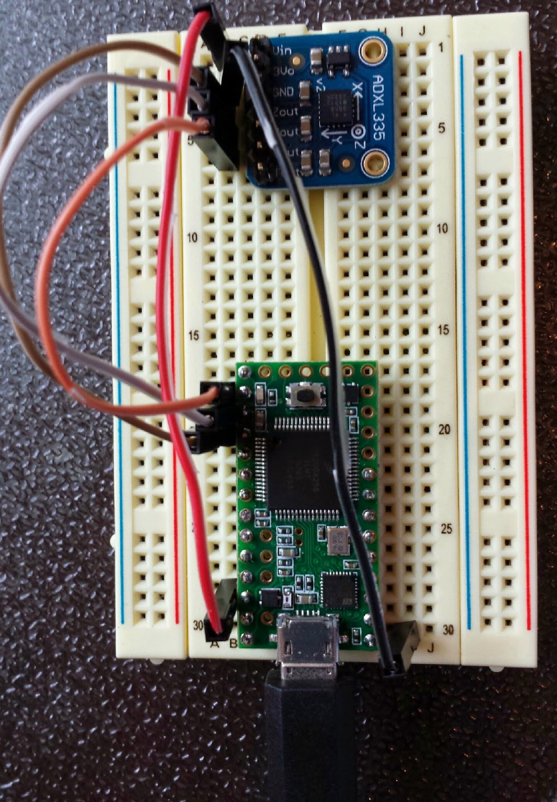
This project only requires a couple parts. You will also need some wire,  a small breadboard and a micro USB cable. You will also want the pin out for the Teensy 3.1.

Parts List


Total Cost  $35


Step 1 - Circuit Setup

I used analog input pins A0, A1, and A2 for the x,y,z outputs from the accelerometer and powered the accelerometer directly from the 3.3V output of the Teensy. I soldered headers onto the the Teensy's side pins to make it breadboard friendly.


Step 2 - Programming Environment Setup

The Teensy can be programmed through the Arduino IDE with the Teensyduino add on and a micro USB cable. Many of the Arduino libraries are also compatible with the Teensy. 
  1. Download and install the Arduino IDE if you do not already have it.
  2. Download and install the Teensyduino add on for the Arduino IDE.
  3. Download the Teensy loader program for your OS .
Next we need to calibrate the Accelerometer.

Step 3 - Accelerometer Calibration 

We need to determine the max and min values for each axis of the accelerometer. To do this, you need get multiple readings with the accelerometer oriented in the min and max positions along each of the axis. The values will be used as constants in the code that will run on the Teensy to get scaled readings.

I used a modified procedure based on the calibration instructions on the Adafruit learning site to calibrate my accelerometer because I didn't want to do any additional hardware setup. 

Compile and Load the Calibration code

  1. Download the ADXL335 Calibration sketch and open it in the Arduino IDE.
  2. Open the calibration sketch in your Arduino IDE. 
  3. Plug in the Teensy micro USB cable.
  4. Select Teensy 3.1 as the board under Tools -> Board -> Teensy 3.1
  5. Verify that the correct COM port is selected for the Teensy under Tools->Serial Port. (It will probably be the only one shown unless there are other COM devices connected to your computer.)
  6. Compile/Verify the sketch by typing Ctrl+R or clicking on the check mark icon near the top left corner.
  7. When the sketch is done compiling, the Teensy Loader will open automatically. 
  8. With the Teensy Loader in Auto mode (the Auto button is green as shown below), press the button on the Teensy board to upload the calibration code.


Perform the Calibration

  1. Open the Serial Monitor under Tools-> Serial Monitor in the Arduino IDE.
  2. Set the baud rate. The baud rate can be set to 38400 using the drop down at the bottom right corner of the Serial Monitor window. 
Measure Z-Max 
  1. Place the Accelerometer circuit on a flat surface to get the Z-max value.
  2. Send a "1" to the Teensy using the Serial Monitor Send feature to run the calibration code. You should see output in the Serial Monitor as shown below. Notice that the upper range for Z is now 612, this is the max value for Z when the board is at rest. The X and Y Min values have changed too, but we are not done with those yet.

Measure Z-Min
  1. Hold the Accelerometer circuit upside down against a flat surface(such as the underside of a table) to get the Z-min value. (Hold it still during the measurement). 
  2. Again, send a "1" to the Teensy using the Serial Monitor Send feature to run the calibration code. A second calibration output will appear in the Serial Monitor as shown below. Now the lower range for Z will have changed, in my measurement, it was measured at 413 as shown below. 

Measure the Y-Max, Y-Min, X-Max, and X-Min Values

Repeat the procedure above with the circuit oriented in the Max and Min positions for the X and Y axis's using the following orientations:

Y-Max:  Y arrow on the accelerometer should be pointing straight up. 
Y-Min:   Y arrow on the accelerometer should be pointing straight down.
X-Max:  X arrow on the accelerometer should be pointing straight up.
X-Min:   X arrow on the accelerometer should be pointing straight down.

The min max values for each axis are retained through calibration runs so the final output will have the min and max ranges for the raw values for each axis. These values will be used as constants in my code to normalize the output values.


Step 4 - Program the Teensy

Now that we have the min max values to use, we use the values in code to send normalized values between 1 and -1 for the x, y, and z orientations detected by the accelerometer.
  1. Download the Teensy Accelerometer Code
  2. Open the TeensyAdxl335.ino sketch and change the min/max values for each axis to the values measured in the calibration above. 
  3. Save and Verify/Compile, and upload the code to the Teensy using the same procedure described above to upload the calibration code.
  4. Use the Serial Monitor to verify the output from the Accelerometer. You should see the out values scrolling. The output should look like the view below.